
- Overview
- Recommended Products
Product Introduction
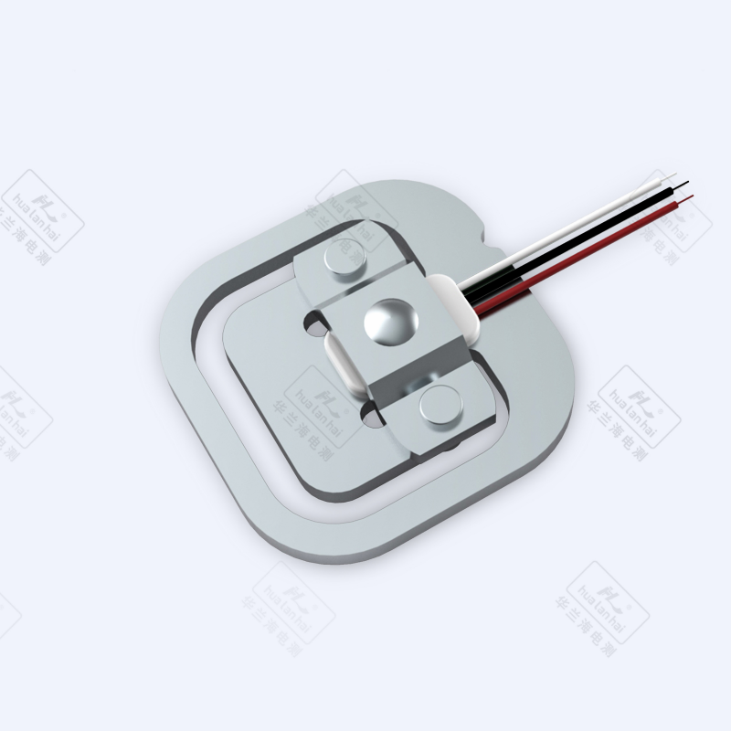
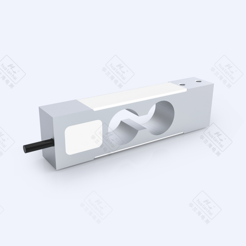
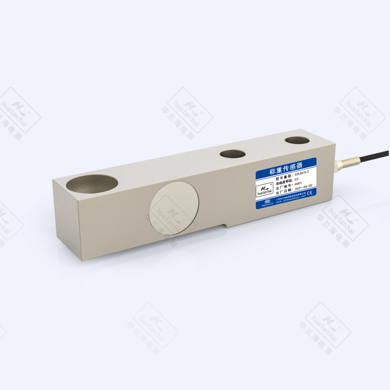
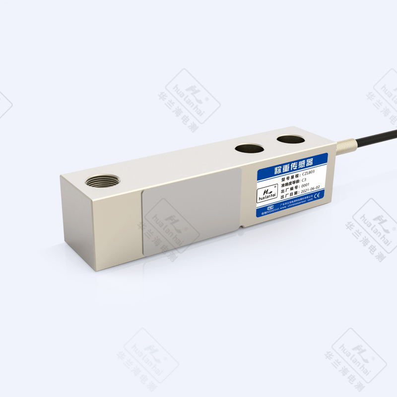
The cantilever beam load cell is a force-sensitive detection element based on the strain resistance principle, with a cantilever beam-shaped elastic body fixed at one end and suspended at the other as its core structure. When subjected to force, the bending deformation of the beam drives the strain gauge to produce resistance changes, which are then converted into standardized electrical signals. It combines advantages such as medium-range load capacity, flexible installation space, and strong impact resistance, and is widely used in scenarios with concentrated forces of medium and low loads, such as industrial material tanks, platform scales, and belt scales. The following provides a detailed explanation from the core dimensions to meet the needs of product selection, technical evaluation, and solution writing:
1. Product Features and Core Functions
Core Features
1) Structural Design: Adopts an integrated cantilever beam structure (beam thickness 8 - 50mm, length 50 - 300mm), with multiple sets of mounting holes at the fixed end to enhance stability. The stress at the loaded end is concentrated in the middle section of the beam, supporting vertical downward concentrated load measurement, with outstanding impact resistance (able to withstand instantaneous impact of 200% - 300% of the rated load) and high stress transfer efficiency.
2) Precision Performance: The accuracy class covers C3 - C6, with mainstream models reaching C3. Nonlinearity error ≤ ±0.02%FS, repeatability error ≤ ±0.01%FS, zero drift ≤ ±0.003%FS/℃, and its accuracy stability is superior to similar sensors in medium-range scenarios of 50kg - 5t.
3) Materials and Protection: The elastic body commonly uses alloy steel (Q235, 40CrNiMoA) or 304/316L stainless steel, with the surface treated by shot blasting and rust removal + nickel plating (alloy steel) or passivation treatment (stainless steel); the protection class is typically IP66/IP67, and industrial heavy-duty models can reach IP68, suitable for complex industrial environments such as dust and humidity.
4)Installation Compatibility: The fixed end supports bolt fastening or welding, and the loaded end can be connected via threads, flanges, or pressure heads, suitable for multi-position installation at the bottom, side, etc. of equipment. Single or multiple units can be used in parallel, with high combination flexibility.
Core Functions
1) Medium-Range Force Measurement: Focuses on static/quasi-dynamic weighing of medium and low loads (response time ≤ 7ms), with a range covering 50kg - 20t, and typical applications concentrated in the 1t - 10t range. Some heavy-duty models can be extended to 50t, meeting the needs of most industrial medium-load scenarios.
2)Standardized Signal Output: Provides analog signals (4 - 20mA, 0 - 5V, 0 - 10V) and digital signals (RS485/Modbus RTU), and some industrial-grade models support the HART protocol, enabling direct connection to PLC, DCS, and weighing management systems without additional signal conditioning modules.
3)Safety Protection Function: Integrates wide-temperature range temperature compensation (-20℃ ~ 80℃), has overload protection (150% - 250% of the rated load, with alloy steel models reaching 300%), explosion-proof models are certified by Ex d IIB T4/Ex ia IIC T6, and some models include cable anti-pull-off connectors.
4) Long-Term Reliability: Fatigue life ≥ 10⁶ cycles of load, with annual drift ≤ ±0.015%FS under rated load, suitable for long-term continuous operation scenarios such as industrial production lines and material tank monitoring.
2. Core Problems Solved
1) Difficulty in Edge Installation of Equipment: Addressing the limitation of traditional sensors requiring symmetrical installation, the "one end fixed" structure of the cantilever beam can be directly installed on the bottom edge of the equipment or the side of the bracket, solving the problem of insufficient installation space at the center of equipment such as silos and platform scales.
2) Measurement of Concentrated Load in Medium Range: In the medium range of 1t - 10t, through the optimized design of beam stress, the measurement error of concentrated load is controlled within ±0.02%FS, meeting the accuracy requirements of medium load scenarios such as industrial batching and finished product weighing.
3) Damage from Dynamic Impact Load: The buffer deformation characteristics of the cantilever beam elastomer can effectively absorb the instantaneous impact caused by material drop and equipment vibration, solving the problems of easy damage and accuracy drift of traditional sensors in dynamic scenarios.
4) Multi-sensor Combined Weighing: The sensors have good consistency (error ≤ ±0.01%FS for the same batch), support 2 - 4 parallel combination weighing, solving the problems of weight superposition and accuracy uniformity in scenarios with distributed forces such as large platform scales and silos.
5) Adaptation to Harsh Industrial Environments: Through the strengthening of alloy steel material and the design of IP67 and above protection levels, the problems of sensor corrosion and signal abnormalities in environments with dust (such as mines), humidity (such as chemical industry), and slight corrosion (such as electroplating) are solved.
3. User Experience
1) High Installation Flexibility: The standardized mounting holes at the fixed end are compatible with various equipment structures, eliminating the need for professional positioning tools. Installation and calibration can be completed using a level, and a single person can complete the fixing and wiring of a single sensor within 20 minutes.
2) Easy Operation and Calibration: Supports one-key zeroing on the weighing instrument, the three-point calibration process (25%, 50%, 100% of rated load) is suitable for medium range scenarios, and the digital model can remotely complete parameter configuration and calibration through the host computer software.
3) Controllable Maintenance Cost: The fully sealed structure reduces dust intrusion, with an average annual failure rate ≤ 0.5%; the core components (strain gauges, terminals) are independently packaged, and local faults can be repaired separately without the need for overall replacement.
4) Stable Data Feedback: Static measurement data fluctuation ≤ ±0.005%FS, responds quickly without lag in quasi-dynamic scenarios (such as belt conveyor); the digital model has a built-in fault diagnosis function, providing real-time alerts for abnormalities such as overload and under-voltage.
5) Strong Combination Adaptability: When multiple sensors are connected in parallel, it supports automatic load distribution, eliminating the need for an additional equalizer, adapting to the design requirements of platform scales and silos of different sizes, and reducing the difficulty of system integration.
4. Typical Application Scenarios
1) Weighing of Industrial Silos/Hoppers
• Chemical Raw Material Tanks: Weighing of 1 - 10t chemical raw material storage tanks, 2 - 4 cantilever beam sensors are symmetrically installed on the tank bottom bracket, the alloy steel material is corrosion-resistant, the IP67 protection is suitable for the humid environment in the workshop, and the accuracy of ±0.02%FS ensures accurate inventory measurement.
• Feed/Flour Hoppers: Weighing of batching hoppers in the grain processing industry, sensors are installed on the support legs at the bottom of the hopper, the anti-impact design copes with the impact of material falling, and cooperates with the control system to achieve accurate feeding.
2) Weighing of Belt Scales/Conveyors
• Industrial Belt Scales: Weighing of bulk material conveying belts in mines and power plants, sensors are installed on the idler bracket, bearing the combined load of the belt and materials, with a response time ≤ 7ms suitable for continuous conveying scenarios, and a measurement accuracy of ±0.1%.
• Conveyor: Used for in-line weighing and sorting in the electronics and food industries. Sensors are embedded at the bottom of the conveyor to detect product weight in real-time and interact with the sorting mechanism. Medium-range accuracy meets the needs of mass production.
3) Small and Medium-sized Truck Scales/Platform Scales
• Workshop Platform Scale: 1-5t workshop turnover platform scale. Four shear beam sensors are installed at the four corners of the scale body. The fixed end is fastened to the ground, and the load-bearing end bears the load of the scale body. The anti-off-center load capacity ensures consistent weighing accuracy at different positions.
• Forklift Truck Scale: Portable forklift weighing device. Sensors are installed on the forklift fork carriage to bear the vertical load of the goods. The alloy steel material is impact-resistant, suitable for dynamic weighing requirements during forklift operations.
4) Force Control of Automation Equipment
• Pressure Monitoring of Stamping Equipment: Pressure control of small stamping machines. Sensors are installed between the stamping head and the machine body to provide real-time feedback of the stamping force value, preventing mold damage caused by overloading. An accuracy of ±0.01%FS ensures stamping quality.
• Force Control of Robot Assembly: Pressure monitoring in the assembly process of industrial robots. Shear beam sensors are integrated at the end of the robotic arm to detect assembly pressure and adjust the action force, suitable for the assembly of automotive parts and electronic components.
5) Special Industry Applications
• Explosion-proof Scenarios: Explosion-proof weighing equipment for the coal mine and oil and gas industries. Ex d IIB T4 explosion-proof shear beam sensors are used and installed in explosion-proof weighing boxes to meet the safety requirements of explosive environments.
• Corrosive Environments: Weighing equipment for the electroplating and chemical industries. Sensors made of 316L stainless steel with surface passivation treatment are corrosion-resistant to acids and alkalis, suitable for scenarios such as electroplating solution concentration detection and chemical reagent weighing.
5. Usage Instructions (Practical Guide)
1) Installation Process
• Preparation: Clean the installation surface (ensure it is flat, free of oil, and the flatness error ≤0.1mm/m), check the sensor appearance (no deformation of the beam body and no damage to the cable), and select M12-M24 specification mounting bolts according to the range.
• Positioning and Fixing: Fasten the fixed end of the sensor to the equipment bracket with bolts to ensure it is firmly fixed without looseness; the load-bearing end should fit the load-bearing structure to ensure that the load acts vertically on the beam body, avoiding lateral and torsional forces.
• Wiring Specification: For analog signals, follow the wiring principle of "red - power +, black - power -, green - signal +, white - signal -"; for digital signals, connect according to the corresponding pins of the Modbus protocol; the wiring should be away from strong interference sources such as frequency converters, with a distance ≥15cm.
• Protection Treatment: For outdoor installation, a rain cover should be added; in a humid environment, the cable joints should be sealed with a waterproof junction box; in a corrosive environment, a special anti-corrosion coating should be applied to the non-load-bearing surface of the sensor.
2) Calibration and Debugging
• Zero Calibration: Turn on the power and preheat for 30 minutes, then execute the "zero calibration" command to ensure that the zero output is within the range of ±0.002%FS. If the deviation is too large, check whether the installation is firm and whether there is lateral force.
• Load Calibration: Place standard weights of 25%, 50%, and 100% of the rated load in sequence, record the output signal values at each point, correct the linear error through calibration software, and ensure that the error at each load point ≤ the allowable value of Class C3 (±0.02%FS).
• Linear Test: Uniformly select 5 test points within the measurement range to verify the linearity of the output signal. The linear error should ≤ ±0.015%FS to ensure the stability of the full-scale accuracy in the mid-range.
3) Routine Maintenance
• Regular Inspection: Clean the dust and oil on the sensor surface monthly, check the tightness of the fixing bolts; perform zero-point calibration once a quarter, and complete full-scale calibration and performance testing annually.
• Fault Handling: When data drifts, first check the power supply voltage (stable at 12-24V DC); when the reading is abnormal, check for overloading (exceeding 300% of the rated load may cause damage) or beam deformation, and replace the sensor if necessary.
6. Selection Method (Precisely Match Requirements)
1) Determination of Core Parameters
• Range Selection: Select a model with a range 1.3-1.6 times the actual maximum load (e.g., for a maximum load of 5t, a 6.5-8t sensor can be selected) to reserve for impact load and safety margin.
• Accuracy Class: Select Class C3 (error ≤ ±0.02%FS) for industrial metrology, Class C6 (error ≤ ±0.03%FS) for general monitoring, and a Class C3 model with a response time ≤ 7ms for dynamic weighing.
• Signal Type: Select analog signals (4-20mA) for traditional control systems, digital signals (RS485) for intelligent systems, and models with wireless transmission modules for industrial IoT scenarios.
2) Environmental Adaptability Selection
• Temperature: Select ordinary models for normal scenarios (-20°C~60°C), high-temperature compensation models for high-temperature scenarios (60°C~120°C), and low-temperature-resistant models for low-temperature scenarios (-40°C~-20°C).
• Medium: Select alloy steel (nickel-plated) for dry environments, 304 stainless steel for humid/slightly corrosive environments, and 316L stainless steel for highly corrosive environments (acid-base solutions).
• Protection Class: ≥IP66 for indoor dry environments, ≥IP67 for outdoor/humid environments, and ≥IP68 for underwater or dust-intensive environments.
3) Installation and System Compatibility
• Installation Method: Select bolt fixing for bottom installation of equipment, flange connection for side installation; when multiple sensors are used in a weighing system, select digital models that support address coding to avoid signal conflicts.
• Compatibility: Confirm that the sensor signal matches the communication protocol of the existing meter/PLC. For example, for Siemens PLC, preferentially select models that support the Profibus protocol to reduce integration difficulty.
4) Confirmation of Additional Requirements
• Certification Requirements: Explosion-proof scenarios require corresponding explosion-proof grade certification (Ex d I for coal mines, Ex ia IIC T6 for chemical industries), metrology scenarios require CMC certification, and export products require OIML certification.
• Special Features: For dynamic weighing, an impact-resistant enhanced type (impact load ≥300%FS) should be selected; for remote monitoring, a model with an NB-IoT/LoRa module should be chosen; for high-temperature scenarios, a dedicated model with a temperature compensation chip should be selected.
Summary
The cantilever beam load cell has core advantages of "precision in medium range, flexible installation, and strong impact resistance", and it mainly addresses issues such as edge installation of equipment, concentrated load measurement, and dynamic impact protection in industrial medium-load scenarios. User experience focuses on convenient installation, worry-free maintenance, and good system compatibility. When selecting a model, it is necessary to first clarify the four core requirements of range, accuracy, installation location, and environment, and then make a decision based on system compatibility and additional functions; during use, lateral force and overload should be avoided, and regular calibration specifications should be strictly followed to ensure long-term stable operation. It is suitable for industrial material tanks, belt scales, small and medium-sized weighing instruments, and other fields, and is the mainstream sensing solution for industrial weighing scenarios with low to medium loads.
Detail Display

Parameters
| Parameter Name | Parameter Value |
| Sensor range | 500kg ~ 5000kg |
| Accuracy class | C2/C3 |
| Comprehensive error | ±0.03 & ±0.02% FS |
| Output sensitivity | 2.0±0.003 mV/V |
| creep | ±0.023 & ±0.016% FS/30min |
| Zero output | ±1.5% FS |
| Input impedance | 350±5Ω |
| Output impedance | 350±3Ω |
| insulation resistance | ≥5000 MΩ(100VDC) |
| Influence of zero temperature | ±0.029 & ±0.019% FS/10℃ |
| Sensitivity temperature effect | ±0.017 & ±0.011% FS/10℃ |
| Temperature compensation range | -10℃ ~ +40 ℃ |
| Operating temperature range | -30℃ ~ +70 ℃ |
| Excitation voltage | 5VDC ~ 12VDC |
| Safe overload range | 150% |
| Limit overload range | 200% |
| Material Science | Alloy Steel |
| Protection level | IP66 |