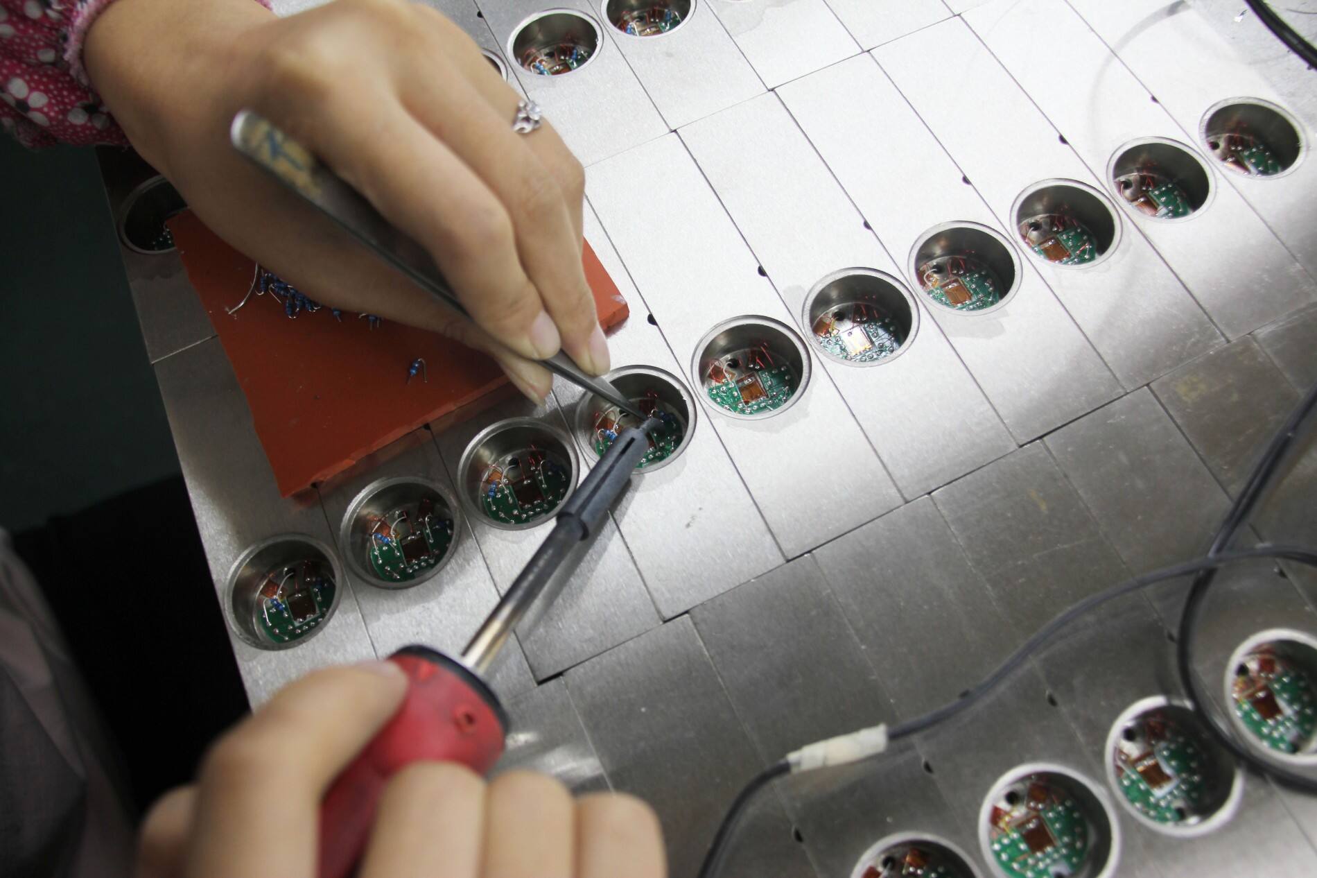
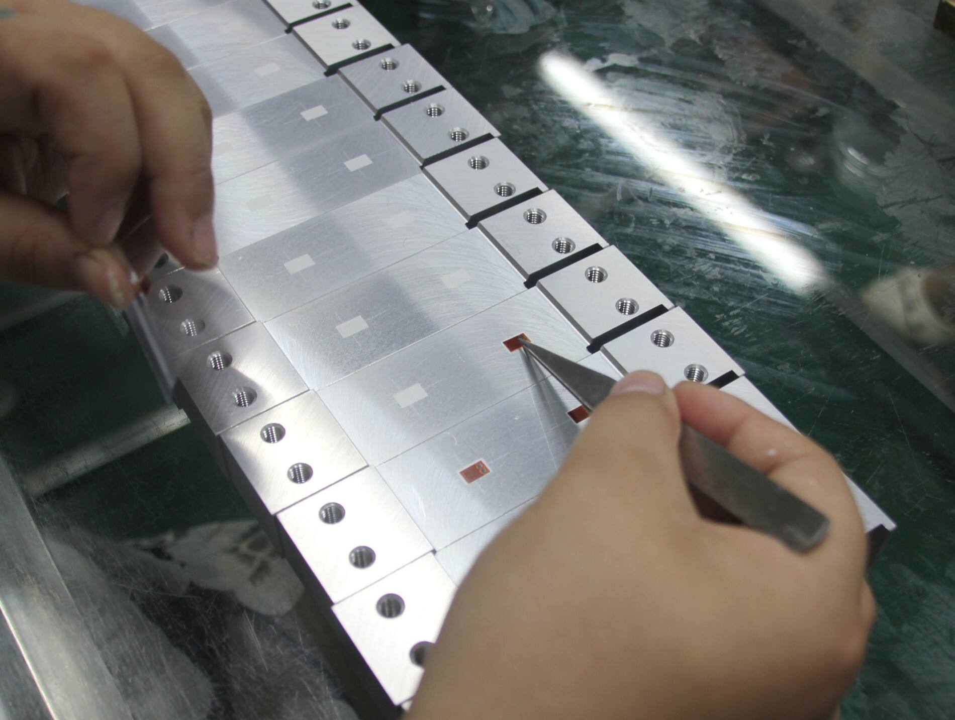
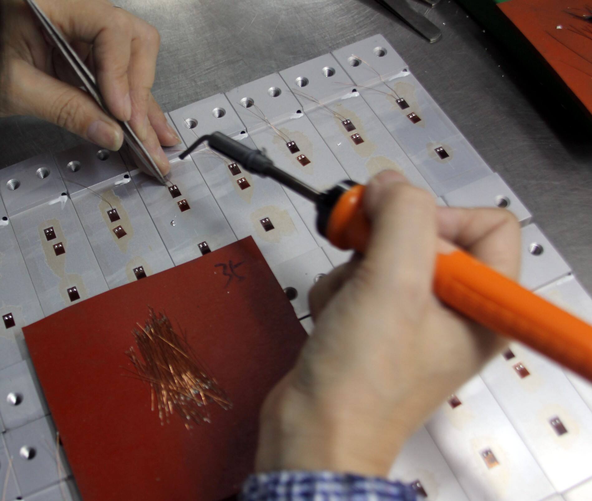
Rezistencë gaugë tensioni (të quajtur galvanometra) janë komponentë themelorë të ndjeshëm që e kthejnë tensionin mekanik të elementeve strukturorë në ndryshime rezistence, të përdorur gjerësisht në qeliza ngarkese , sensorë forcash, monitorim të shëndetit strukturor, testime në avacion dhe fusha të tjera. Zgjedhja e tyre përcakton drejtpërdrejt saktësinë, stabilitetin dhe jetëgjatësinë e sistemit të matjes. Logjika themelore është "përputhja dydrejtesh e karakteristikave të deformimit me mjedisin e përdorimit"—duke shmangur humbjen e kostos si pasojë e tepërsisë së parametrave dhe parandaluar dështimin e matjes për shkak të mungesës së performancës. Më poshtë është një metodë zgjedhjeje e plotë procesi, e cila kombinon parametrat teknikë, adaptimin me mjedisin dhe pikat kyçe praktike për t'u asistuar në zgjedhjen e saktë.

Hapi 1: Qartësoni Kërkesat Themelore të Matjes dhe Skenarët e Aplikimit (Parakushti për Zgjedhje)
Përpara përzgjedhjes, është e nevojshme të përcaktohet "cila deformim të matësh, në cilin ambient të matësh dhe si të instalojësh", që është baza për përzgjedhjen e parametrave të mëvonshëm dhe i shmang përfoljen e blind të parametrave me performancë të lartë.
1. Përkufizimi i Kërkesave Themelore të Matjes
- Lloji dhe diapazoni i deformimit: Qartësoni natyrën e deformimit të komponentit të matur (deformim statik si deformimi nga peshë strukturore, deformim dinamik si deformim nga vibracioni mekanik) dhe vlerën maksimale të deformimit, duke parashikuar një rezervë sigurie prej 1,2~1,5 herë. Shembull: Nëse deformimi maksimal aktual është 1000με, duhet të përzgjidhet një sensor deformimi me diapazon 1200~1500με; për deformimin dinamik (si ngarkesa goditjeje), rekomandohet të parashikohet një faktor sigurie prej 1,5~2 herë për të shmangur dëmtimin e rrjetit ndjeshëm nga ngarkesa momentale.
- Kërkesa për saktësi: A është monitorim kualitativ (si paralajmërimi i hershëm për çarje strukturore), analizë kuantitative (si kalibrimi i sensorëve) apo matje e saktë (si testimi i tensionit në laborator)? Shembull: Gajtërat e deformimit për qeliza të ngarkesës duhet të plotësojnë një gabim ndjeshmërie prej ±0,1%, monitorimi i shëndetit strukturor mund të ketë një gabim ≤±0,5%, dhe matja e saktësisë në laborator kërkon ≤±0,05%.
- Drejtimi i forcës: A është pjesa e nënshtruar një force unidireksionale (si përkulja e trarit konsolë), force bidireksionale (si pjesë mekanike në gjendje të rëndesës plane) apo force shumëdireksionale (si nyjet strukturore komplekse)? Zgjidhni gajtëra uniaxiale për forcat unidireksionale, dhe gajtëra biaxiale (kënd të drejtë, rosetë deformimesh) ose shumëaxhiale për forcat bidireksionale/shumëdireksionale.
- Frekuenca e matjes: Për matjen dinamike, duhet qartësuar diapazoni i frekuencës së sinjalit të deformimit. Frekuenca e përgjigjes së sensorit të deformimit duhet të jetë ≥3 herë frekuenca e sinjalit të matur (për të shmangur shtrembërimin e sinjalit). Shembull: Për të matur deformimin nga vibracionet me 50 Hz, duhet të përzgjedhet një sensor deformimi me frekuencë përgjigjeje ≥150 Hz.
2. Instalimi dhe Kushtet Strukturore
- Karakteristikat e sipërfaqes së komponentit: A është sipërfaqja e komponentit e rrafshët, e lakuar (cili është rrezja e lakimit) apo me formë speciale? Sensorët e fleksibël të deformimit (siç janë ato me folje metalike) janë të përshtatshëm për komponentët e lakuar, dhe kërkohen sensorë me gjatësi celule shumë të shkurtër për rreze lakimi të vogla (≤10 mm); llojet me ngjitje të fortë në substrat janë të përshtatshme për sipërfaqe të rugosura.
- Hapësira e instalimit: Janë të nevojshme indikatorë të miniaturizuar të ngarkesës (gjatësi rethi ≤2 mm) për zonat e ngushta të pjesëve (si p.sh. bishtet e pjesëve saktësise), ndërsa për pjesët me madhësi të madhe mund të zgjidhen indikatorë me gjatësi mesatare ose të gjatë rethi në varësi të njëformësisë së ngarkesës.
- Metoda e instalimit: A është montimi i lidhjes në temperaturë ambienti, montimi me valëzim në temperaturë të lartë apo ngjitje e përkohshme? Për skenarët me temperaturë të lartë kërkohen indikatorë të valëzueshëm, ndërsa për monitorimin e përkohshëm mund të përdoren indikatorë me montim magnetik.
3. Kushtet e punës në mjedis
- Rangu i temperaturës: Duhet të qartësohet intervali i temperaturës normale (-20℃~60℃), temperaturës mesatare (60℃~200℃), temperaturës së lartë (200℃~1000℃) ose temperaturës së ulët (<-20℃). Rangu i kompensimit të temperaturës së indikatorit duhet të mbulojë plotësisht temperaturën aktuale për të shmangur ndikimin në saktësi nga zhvendosja e temperaturës.
- Mjedisi i mesëm: A ka lagështi (si p.sh. nën ujë, salla të lagura), korrozion (si gazet acid-bazike, ndotja me vaj në sallë kimike), pluhur ose rrezatim të fortë? Për mjediset e lagur kërkohen indikatorë të rezistencës hidroizoluese, për mjediset korrozive kërkohen materiale rezistente ndaj korrozionit (si rrjetat e legurave nikel-kromi, bazat poliimid) të kombinuara me trajtim izolues.
- Faktorët e ndërhyrjes: A ka ndërhyrje të forta elektromagnetike (siç janë motorët pranë, pajisjet me tension të lartë) ose ndikim nga dridhjet? Matësit e tendosjes me shtresa mbrojtëse kërkohen për skenarë të ndërhyrjes së fortë, dhe llojet me rezistencë të mirë të substrateve dhe ngjitësve kërkohen për skenarë të ndikimit nga dridhjet.

Hapi 2: Zgjedhja e Parametrave Teknikë Bazë (Përputhja e Sakta e Kërkesave)
Pasi të jetë bërë e qartë kërkesa, fokusoju tek parametrat teknikë themelorë të indikatorit të rezistencës, i cili është lidhja qendrore e zgjedhjes dhe përcakton drejtpërdrejt performancën e matjes.
1. Parametrat Kryesorë të Fletës Sensitive (Përcaktojnë Performancën Bazike të Matjes)
- Vlera e rezistencës: Vlera konvencionale e rezistencës së galvanometrave të deformimit është 120Ω (e përputhshme me shumicën e galvanometrave të deformimit, me përdorshmëri më të fortë), por ka edhe specifikime si 350Ω dhe 1000Ω. Galvanometrat e deformimit me rezistencë të lartë janë të përshtatshëm për sisteme me konsum të ulët energjie, ndërsa galvanometrat 120Ω kanë efikasitetin më të lartë të kostos në skenarë industriale. Gjatë zgjedhjes, sigurohuni që vlera e rezistencës së galvanometrit të përputhet me rezistencën hyrëse të galvanometrit (devijimi ≤±5%) për të shmangur zvogëlimin e sinjalit.
- Faktori i matjes: Tregon marrëdhënien proporcionale midis deformimit dhe ndryshimit të rezistencës (vlera konvencionale 2.0±0.02), i cili është një parametër kyç për llogaritjen e vlerës së deformimit. Gjatë zgjedhjes, duhet të jepet përparësi galvetave të rezistencës me konzistencë të mirë të faktorit të matjes (devijimi i partisë ≤±1%), veçanërisht kur përdoren disa galva në një qark të mbushur (si qarku i plotë i një qelije ngarkese), ku konzistenca e dobët do të çojë në rritjen e gabimeve të matjes.
- Gjatësia dhe gjerësia e rrjetit: Gjatësia e rrjetit përcakton "rangu mesatar të matjes" të galvës së rezistencës. Gjatësia e vogël e rrjetit (0.2~2 mm) është e përshtatshme për matjen e deformimit lokal (si majat e çarjeve), gjatësia mesatare e rrjetit (3~10 mm) është e përshtatshme për pjesët konvencionale, dhe gjatësia e madhe e rrjetit (10~100 mm) është e përshtatshme për pjesët me madhësi të madhe me gradientë të vegjël deformimi. Gjerësia e rrjetit duhet të përputhet me drejtimin e forcës së pjesës: gjerësi e ngushtë e rrjetit për forcë njëdrejtimore, dhe gjerësi e gjerë e rrjetit ose strukturë rosete deformimi për forcë dydrejtimore.
-
Materiali i rrjetës së ndjeshme:
- Legura bakër-nikël (Constantan): E preferuar për skenarë me temperaturë normale (-20℃~150℃), me koeficient të vogël termik dhe stabilitet të mirë, e përshtatshme për qeliza matëse ngarkese dhe monitorim strukturash;
- Legura nikël-krom (Karma): Për skenarë me temperaturë mesatare dhe të lartë (-50℃~400℃), me ndjeshmëri të lartë, e përshtatshme për motorë dhe monitorim tubash me temperaturë të lartë;
- Legura platin-iridium: Për skenarë me temperaturë të lartë (400℃~1000℃), me rezistencë të fortë ndaj korrozionit, e përshtatshme për pajisje ajrore dhe metalurgjike;
- Materialet gjysmëpërçuese: Ndjeshmëri ekstremisht e lartë (50~100 herë më e madhe se sa e metaleve), por stabilitet i dobët termik, e përshtatshme për matje precizësisht në laborator.
2. Parametrat e Nënstratit dhe të Ngjitësit (Përcaktojnë Përshtatshmërinë me Mjedisin)
-
Materiali i nënstratit:
- Nënstrat letre: Kostë e ulët, e lehtë për ngjitje, e përshtatshme për mjedise normale dhe të thata (≤60℃), si monitorimi i përkohshëm i pajisjeve civile;
- Nënstrati me rezinë fenolike: Rezistencë ndaj temperaturës 120℃, rezistencë e mirë ndaj yndyrnave, i përshtatshëm për skenarë të zakonshëm të makinave industriale;
- Nënstrati me poliimid: Rezistencë ndaj temperaturës 250℃, rezistencë ndaj korrozionit dhe ujit, i përshtatshëm për skenarë kimikë, me lagështi dhe me temperaturë mesatare-të lartë;
- Nënstrati me pllakë qeramike: Rezistencë ndaj temperaturës mbi 1000℃, i përshtatshëm për mjedise ekstreme si furrat me temperaturë të lartë dhe motorët ajronautikë.
- Lloji i ngjitësit: Duhet të përputhet me materialin e nënstratit dhe temperaturën e punës. Për skenarët me temperaturë normale përdoren ngjitës bazë cianoakrilati (me tharje të shpejtë), për skenarët me temperaturë mesatare ngjitës me rezinë epoksidike (rezistencë ndaj temperaturës 150℃), dhe për skenarët me temperaturë të lartë ngjitës inorganikë (rezistencë ndaj temperaturës mbi 500℃). Fortësia e prerjes së ngjitësit duhet të jetë ≥2MPa për të shmangur zhdukkjen e indikatorit të tensionit.
3. Parametrat e kompensimit të temperaturës (Përcakton stabilizimin e matjes)
-
Metoda e kompensimit të temperaturës:
- Gaugët e vetë-kompensuar të tensionit: Duke zgjedhur materiale të rrjetit të ndjeshëm, ndryshimi i rezistencës i shkaktuar nga temperatura kompensohet nga zgjerimi termik i pjesës, të përshtatshme për pjesët me material të vetëm (siç është çeliku, aluminiumi), të lehta për tu instaluar dhe të preferuara për skenarë industriale;
- Kompensimi me gauge shtesë: Gaugë shtesë të njëjtë me ato punuese ngjitën në pjesë identike por pa ngarkesë, dhe gabimet nga temperatura kompensohen përmes qarkove, të përshtatshme për fusha komplekse termike ose pjesë me shumë materiale.
- Dijapazoni i kompensimit të temperaturës: Duhet të mbulojë dijapazonin aktual të punës në temperaturë. Shembull: Në një ambient prodhimi prej -10℃~80℃, duhet të zgjidhet një gauge tensioni me dijapazon kompensimi prej -20℃~100℃ për të siguruar rezervë termike.
4. Struktura dhe parametrat e kabllos (Përcakton Instalimin dhe Transmetimin e Sinjalit)
-
Struktura e gauges së tensionit:
- Gaugat me një bosht deformimi: Për skenare me forca në një drejtim (si p.sh. trarë konsolë, vrima tërheqëse), strukturë e thjeshtë dhe kosto e ulët;
- Gaugat biaxiale (gaugat me kënd të drejtë): Për skenare me forca dy-drejtimore (si p.sh. komponente të rrafshit të tensionit), mund të masin deformimet në dy drejtime vertikale njëkohësisht;
- Rojet e deformimit (45°, 60°): Për skenare me forca shumë-drejtimore (si nyjet strukturore, pjesë komplekse), mund të llogarisin deformimin kryesor dhe drejtimin e tensionit kryesor, të përshtatshme për analizën e tensioneve.
- Specifikimet e kabllos: Materialet e kabllove janë zakonisht tela prej bakri me pluhur argjendi. Për kushte normale të temperaturës përdoren tela me izolim PVC, kurse për kushte me temperaturë të lartë përdoren tela me izolim PTFE. Gjatësia e kabllot duhet të përputhet me distancën e matjes. Për transmetim të largët (10 m), kërkohen kabllo me shtresa mbrojtëse që të shmangen ndërhyrjet elektromagnetike.

Hapi 3: Përshtatja sipas skenarit dhe shmangia e gabimeve në zgjedhje
Zgjidhni sensorët e deformimit sipas karakteristikave të skenareve të ndryshme aplikimi dhe shmangni gabimet e zakonshme gjatë zgjedhjes për të siguruar qëndrueshmërinë dhe besueshmërinë e sistemit të matjes.
1. Shembuj të Zgjedhjes së Skenarëve Tipik
| Larg Skenariu |
Kërkesat Kryesore |
Parametrat e Rekomanduar të Indikatorit të Tensionit |
| Celës i Ngarkesës (Trup Elastik Prej Çeliku) |
Tension statik, saktësi ±0,1%, temperaturë normale dhe e thatë |
Fletë konstantane, 120Ω, faktor tregues 2,0±0,02, gjatësi fleti 5 mm, bazë poliimide, kompensim i vetvetishëm (kompensim çeliku) |
| Monitorimi i Stresit në Pijet Kimike (Ambient Acido-Bazik) |
Tension dinamik, rezistencë ndaj korrozionit dhe ujit, temperaturë -10℃~80℃ |
Fletë nikel-kromi, 350Ω, gjatësi fleti 10 mm, bazë poliimide, mbulesë rezistente ndaj ujit, kabllo me ekran, kompensim i vetvetishëm |
| Monitorimi me Temperaturë të Lartë i Turbinave të Motorit (300℃) |
Deformim me temperaturë të lartë, frekuencë përgjigjeje ≥200Hz |
Fletë me pllazhë platin-iridium, 1000Ω, gjatësi fletëje 3mm, bazë prej keramike, instalim me bronzim, sensor kompensimi me temperaturë të lartë |
| Analiza e tensionit të komponentëve metalikë në laborator |
Deformim shumë-drejtimor, saktësi ±0,05%, temperaturë e zakonshme |
Rosete deformimi prej konstantani (45°), 120Ω, gjatësi fletëje 2mm, bazë prej reçine fenolike, kompensim me sensor kompensimi |
2. Gabimet e Zakonshme të Zgjedhjes dhe Metodat për t’i Shmangur
- Gabim 1: Të fokusohesh vetëm në faktorin e matësit dhe të injorosh konzistencën – kur përdoren shumë matës në një urë, madje edhe nëse faktori i matësit të një matësi të vetëm i plotëson standardet, devijimet e mëdha të serisë (±1%) do të shkaktojnë mosbaraspeshë të urës dhe rritje të paparalajmëruar të gabimeve të matjes. Parandalimi: Kërkoni furnitorët të sigurojnë raporte testimi të faktorit të matësit për matësit e deformimit të së njëjtës seri, dhe kontrolloni devijimin brenda ±0.5%.
- Gabim 2: Përputhja midis gjatësisë së rrjetit dhe gradientit të deformimit—zgjedhja e sensorëve të deformimit me gjatësi të madhe të rrjetit në zonat vendore të koncentrimit të deformimit, si p.sh. majat e çarjeve, do të sjellë "mesatare" të vlerave të matura dhe dështimin për të pasqyruar deformimin reale. Parandalimi: Zgjidhni gjatësi rrjeti ≤2 mm për zonat me gradient të lartë deformimi dhe 5~10 mm për zonat me deformim uniform.
- Gabim 3: Shpërflytësimi i përputhjes midis kompensimit të temperaturës dhe materialit të pjesës—përdorimi i sensorëve të deformimit të kompensuar për çelik në pjesë të aluminiumit do të shkaktojë gabime serioze të temperaturës për shkak të dallimeve në koeficientët e zgjerimit termik. Parandalimi: Zgjidhni sensorë të deformimit me vetë-kompensim të llojeve përkatëse të kompensimit sipas materialit të pjesës (çelik, alumin, bakër, etj.).
- Gabimi 4: Përdorimi i sensorëve të tensionit me bazë letre në mjedise të lagështa pa trajtim sigimesh do të shkaktojë dështimin e bazës së tyre nga lagështia për një kohë të shkurtër. Parandalimi: Zgjidhni materiale bazike të përshtatshme sipas klasës së mjedisit (të lagësht, korrozive, me temperaturë të lartë) dhe shtoni shtresa sigimesh rezistente ndaj ujit nëse është e nevojshme.
Hapi 4: Shënime shtesë për zgjedhjen praktike
- Përputhshmëria e urës: Kur disa sensorë formojnë një qark të plotë urë ose gjysmë-urë, sigurohuni që vlerat e rezistencës, faktori i sensorit dhe karakteristikat termike të sensorëve të jenë të njëjta. Këshillohet të zgjidhen nga i njëjti partinë për të zvogëluar gabimet e urës.
- Kërkesat e kalibrimit: Për sensorët e përdorur në transaksione tregtare (si p.sh. qeliza matëse ngarkese) ose matje të sakta, zgjidhni produkte nga marka me gjurmueshmëri të garantuar, të cilat kanë kaluar certifikim metrikor, për të lehtësuar kalibrimin e mëtejshëm të sistemit.
- Përputhja e procesit të instalimit: Për pjesët e lakuar, konfirmo paraprakisht performancën e lakimit të sensorit të tensionit (rrezja e lakimit ≤ rrezja e lakimit të pjesës). Për sensorët e tensionit që mund të bashkohen me saldim, përdor pajisjet dhe proceset përkatëse të soldimit.
- Mbështetja nga furnitori: Prioriteti duhet t'i jepet furnitorëve që ofrojnë mbështetje teknike. Njoftojini për materialin e pjesës, kushtet e forcës dhe parametrat ambientalë për të marrë rekomandime më të sakta zgjedhjeje dhe për të shmangur zgjedhjen e pavetëdijshme të pavarur.
Përmbledhje: Logjika kryesore e zgjedhjes së sensorit rezistiv të tensionit
Esencia e zgjedhjes së galvanometrit të rezistencës është një unazë e mbyllur e "dekompozimit të kërkesave → përputhjes së parametrave → verifikimit të skenarit": fillimisht dekomponohen katër kërkesat themelore të "dijes së deformacionit, saktësisë, mjedisit dhe instalimit", pastaj përputhen në mënyrë të synuar parametrat kyçë si rrjeti i ndjeshëm, bazës dhe kompensimi i temperaturës, dhe në fund verifikohet arsyeshmëria e zgjedhjes përmes shembujsh të skenarit dhe shmangies së gabimeve.
Nëse jeni ende të paqartë për zgjedhjen, mund t'i jepni furnitorit informacionin vijues: ① Lënda e pjesës dhe lloji i forcës (njëbosht/dybosht); ② Vlera maksimale e deformacionit dhe kërkesa për saktësi; ③ Temperatura e punës dhe mjedisi medium; ④ Hapësira dhe metoda e instalimit. Furnitori mund të identifikojë shpejt modelin e përshtatshëm.


