
- Overview
- Recommended Products
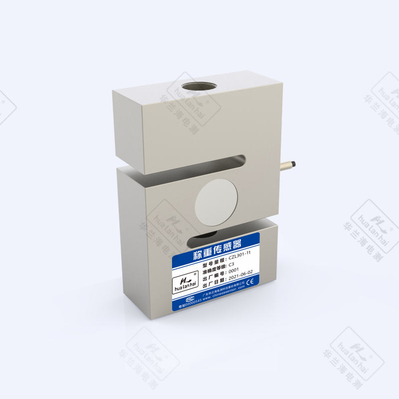
Product Introduction
The S-type load cell is a force-sensitive detection element based on the strain-resistive principle, with a symmetric S-shaped elastomer as its core structure. When subjected to force, the elastomer's tensile or compressive deformation drives the strain gauge to produce resistance changes, which are then converted into standardized electrical signals. It combines advantages such as bidirectional force bearing, flexible installation, and stable accuracy, and is widely used in measurement scenarios for tensile, compressive, and composite forces in medium and low loads. The following details are presented from the core dimensions to meet the needs of product selection, technical evaluation, and solution writing:
1. Product Features and Functions
Core Features
• Structural Design: Adopts an integrated S-shaped elastomer structure (thickness 5-30mm, length 30-200mm), with concentrated and symmetrical stress distribution, supports bidirectional force (both tension and compression can be measured), has strong anti-torsion and anti-transverse force capabilities (can withstand transverse forces of ±10%-±15% of the rated load), and high force transmission efficiency.
• Precision Performance: Accuracy grades cover C2-C6, with mainstream models reaching C3, non-linear error ≤±0.02%FS, repeatability error ≤±0.01%FS, zero drift ≤±0.003%FS/℃, and small precision attenuation in dynamic measurement scenarios of small and medium loads.
• Materials and Protection: The elastomer is commonly made of high-strength alloy steel (yield strength ≥850MPa) or 304/316L stainless steel, with the surface treated by nickel plating or plastic spraying (passivation treatment for corrosion-resistant types); the protection level is usually IP65/IP67, and customized models for humid environments can reach IP68, suitable for general industrial and some special environments.
• Installation Compatibility: Both ends are designed with internal threads, external threads, or lifting ring structures, supporting various installation methods such as hooks, lifting rings, and flanges, with flexible installation space, adaptable to multi-directional force scenarios such as vertical, horizontal, and inclined, and mainly used independently.
Core Functions
• Bidirectional Force Measurement: Supports static/dynamic tension and compression measurement (response time ≤6ms), with a measuring range covering 0.01t-50t, conventional applications concentrated in the 0.1t-20t range, and some high-precision models capable of measuring small ranges of 0.001t.
• Standardized Signal Output: Provides analog signals (4-20mA, 0-5V, 0-10V) and digital signals (RS485/Modbus RTU), and some intelligent models support the Profibus protocol, enabling direct connection to weighing instruments, PLCs, industrial touch screens, and other devices.
• Safety and Protection Functions: Integrates wide temperature range temperature compensation (-20℃~80℃), has overload protection (120%-200% of the rated load, usually 150% in tension scenarios), and some models include anti-torsion positioning pins and cable anti-pull-off joint designs.
• Long-Term Stability: Fatigue life ≥10⁶ cycles of load, annual drift ≤±0.02%FS under rated load, suitable for intermittent or continuous force monitoring scenarios.
2. Core Problems Solved
• Difficulty in Bidirectional Force Measurement: Addressing the limitation of traditional sensors that can only measure force in one direction, the S-shaped structure can accurately measure both tension and compression forces simultaneously (such as force value changes during material lifting and lowering), meeting the demand for bidirectional force monitoring in scenarios like hoisting and traction.
• Adaptability to Complex Installation Scenarios: With flexible connection methods and a compact structure, it solves the installation challenges in equipment with limited space and multi-angle force application (such as weighing of inclined hoppers and tension monitoring of suspended conveyor lines), eliminating the need for large-scale modification of equipment structure.
• Inadequate Accuracy in Light Load/Small Range: In the small range of 0.1t - 5t, by optimizing the bonding position of strain gauges and the stress design of the elastomer, the measurement error is controlled within ±0.01%FS, meeting the high-precision requirements of light load applications in laboratories, food processing, etc.
• Monitoring of Dynamic Tension Fluctuations: With a response time ≤6ms, it can accurately capture tension fluctuations during continuous production processes of cables, films, etc., solving product quality problems caused by unstable tension in industries such as textiles and printing.
• Compatibility Issues in Multi-Equipment Collaboration: Standardized signal output and support for multiple protocols solve the docking obstacles with control systems of different brands (such as Siemens S7 series PLCs and Delta DCS), reducing errors and costs in signal conversion.
3. User Experience
• Installation Convenience: Standardized threaded/eyelet interfaces, with standard connecting parts (such as bolts and shackles), do not require special installation tools. A single person can complete the installation and positioning of a single sensor within 15 minutes, with relatively low requirements for the flatness of the installation surface (flatness error ≤0.1mm/m is sufficient).
• Operation and Calibration: Supports one-key zeroing on the weighing instrument, simplifies the two-point calibration process (only requires standard weights of 10% and 100% of the rated load), and digital models can be remotely calibrated via mobile APP or host computer, enabling non-professionals to operate quickly.
• Controllable Maintenance Cost: The sealed structure effectively isolates dust and moisture, with an annual average failure rate ≤0.4%; the modular design of core components (strain gauges, terminal blocks) allows for individual replacement of local faults, reducing overall replacement costs.
• Intuitive Data Feedback: Static measurement data fluctuation ≤±0.005%FS, with no obvious lag in dynamic scenarios; digital models come with built-in fault alarm prompts for overload, under-voltage, etc., visually presented through indicator lights or software interfaces for easy and quick troubleshooting.
• Flexible Scenario Adaptability: The same sensor can switch between tension/compression measurement modes without replacing hardware, meeting the needs of multi-process shared equipment and improving equipment utilization.
4. Typical Application Scenarios
1) Tensile/ Tension Measurement Scenarios
• Cable/Rope Tension Control: Tension monitoring of wire drawing machines in the textile and cable industries. S-type sensors are connected in series to the traction mechanism, providing real-time feedback on tension values and adjusting the traction speed in a coordinated manner to ensure uniform cable diameter.
• Material Tensile Testing: Tensile measurement of material testing machines in laboratories. C2 precision models can meet the requirements for tensile strength testing of materials such as metal wires and plastic films, with data repeatability error ≤±0.01%.
• Tension Monitoring of Lifting Equipment: Load limit control for small cranes and electric hoists. Installed between the hook and the boom, it triggers an alarm and cuts off power when overloaded to ensure operational safety.
2) Suspended Weighing Scenarios
• Suspended Hopper/Tank Weighing: Weighing of suspended batching tanks in the chemical and feed industries. Single or two sensors are symmetrically suspended and installed to address the issue of insufficient floor space, with an accuracy of up to ±0.02%FS.
• Suspended Weighing in Food Processing: Suspended weighing and sorting in the slaughter and aquatic product industries. Stainless steel (316L) models meet food hygiene standards, are easy to clean and disinfect, and are suitable for assembly line operations.
3) Manufacturing of Small and Medium-sized Weighing Instruments
• Hook Scales/Portable Scales: Core sensing units for 0.5t-20t hook scales. Their compact structure is suitable for scale body design, and their impact resistance can handle instantaneous overloads during lifting operations.
• Belt Scales/Dynamic Scales: Dynamic weighing modules for conveyor belts. Installed on the belt roller support, they indirectly calculate the weight of materials by measuring belt tension, adapting to continuous conveying scenarios.
4) Scientific Research and Experimental Equipment
• Biomechanical Testing: Force value monitoring of medical rehabilitation equipment (such as prosthetic force testing). Small-range, high-precision models (0.01t-1t) can capture subtle force value changes.
• Force Control at the End of Robots: Force feedback for the grasping mechanism of industrial robots. By measuring the grasping force, the clamping force is adjusted to avoid damaging fragile workpieces (such as glass and ceramics).
5) Special Industry Applications
• Pharmaceutical Industry: Pressure control of pharmaceutical capsule filling machines. Hygienic-grade stainless steel models meet GMP standards, precisely controlling filling pressure to ensure uniform capsule dosage.
• Printing and Packaging Industry: Tension monitoring of film printing machines. Real-time adjustment of unwinding and rewinding speeds prevents film stretching, deformation, or breakage, improving printing accuracy.
5. Usage Instructions (Practical Guide)
1) Installation Process
• Preparation: Clean the installation connection points (remove burrs and oil stains), check the appearance of the sensor (no deformation of the elastomer, no damage to the cable), and select the correct connection method according to the force direction (choose a lifting ring for tension, and bolt fixation for compression).
• Positioning and Fixing: Ensure that the load is transmitted along the axial direction of the sensor to avoid lateral and torsional forces; use a torque wrench when tightening bolts (10-30 N·m is recommended for alloy steel sensors, 8-25 N·m for stainless steel) to prevent over-tightening from damaging the threads.
• Wiring Specification: For analog signals, follow the rule of "red - power +, black - power -, green - signal +, white - signal -"; for digital signals, connect according to the Modbus pin correspondence; the cable should be securely fixed to avoid being pulled by force, and the wiring should be kept away from strong interference sources such as frequency converters (distance ≥ 20 cm).
• Protection Treatment: For outdoor installation, a rain cover should be added; in a humid/corrosive environment, place the cable connector in a waterproof junction box, and the sensor surface can be coated with food-grade anti-corrosion oil (for the food industry).
2) Calibration and Debugging
• Zero Calibration: Turn on the power and preheat for 15 minutes, execute the "zero calibration" command, ensure that the zero output is within ±0.002%FS, and if the deviation is too large, check whether there is lateral force in the installation.
• Load Calibration: Place standard weights of 10%, 50%, and 100% of the rated load in sequence, record the output signals at each point, correct the linear error through calibration software, and ensure that the error ≤ the allowable value of the corresponding accuracy level (C3 level ≤ ±0.02%FS).
• Dynamic Debugging: In dynamic scenarios such as tension monitoring, adjust the instrument filtering frequency (5-12 Hz) to balance the response speed and data stability, and avoid false alarms caused by high-frequency fluctuations.
3) Routine Maintenance
• Regular Inspection: Clean the sensor surface monthly, check whether the threaded connection is loose; perform zero calibration once a quarter, complete full-scale calibration once a year, and record the calibration data for future reference.
• Fault Handling: When data drifts, first check the power supply voltage (stable at 12-24 V DC); when there is no signal output, check whether the cable is broken or the sensor is overloaded (over 200% of the rated load is likely to cause damage).
6. Selection Method (Precisely Match Requirements)
1) Determination of Core Parameters
• Range Selection: Select the model according to 1.2 - 1.5 times the actual maximum force value (e.g., if the maximum tensile force is 8t, a 10 - 12t sensor can be selected). For tensile force scenarios, an additional 10% overload margin should be reserved to avoid damage from impact loads.
• Accuracy Class: Select Class C2 (error ≤ ±0.01%FS) for laboratory testing, Class C3 (error ≤ ±0.02%FS) for industrial metrology, and Class C6 (error ≤ ±0.03%FS) for general monitoring. • Signal Type: Select analog signals (4 - 20mA) for traditional weighing instruments, digital signals (RS485) for intelligent systems, and intelligent models with wireless transmission (WiFi/4G) for industrial IoT scenarios.
2) Selection Based on Environmental Adaptability
• Temperature: Select ordinary models for normal scenarios (-20°C ~ 60°C), high-temperature compensation models for high-temperature scenarios (60°C ~ 100°C), and low-temperature-resistant models for low-temperature scenarios (-40°C ~ -20°C).
• Medium: Select alloy steel (surface powder-coated) for dry environments, 304 stainless steel for wet/food industries, and 316L stainless steel for chemical corrosion environments.
• Protection Class: ≥IP65 for indoor dry environments, ≥IP67 for outdoor/wet environments, and ≥IP68 for underwater or dust-intensive environments.
3) Installation and System Compatibility
• Installation Method: Select eyelet connections for tensile force scenarios, bolt fixing for pressure scenarios, and models with locating pins for inclined force applications; for limited space, prioritize compact models with a length ≤50mm.
• Compatibility: Confirm that the sensor signal matches the communication protocol of the existing instrument/PLC. When multiple sensors work together, select digital models that support address setting to avoid signal conflicts.
4) Confirmation of Additional Requirements
• Certification Requirements: Explosion-proof scenarios require Ex ia IIC T6/Ex d IIB T4 certification, the food industry requires FDA/GMP certification, and metrology scenarios require CMC certification.
• Special Functions: Select models with a response time ≤5ms for dynamic tension monitoring, models with an NB-IoT module for remote monitoring, and hygienic-grade models with dead-angle-free polishing (Ra ≤0.8μm) for hygienic scenarios.
Summary
S-type load cells feature "bidirectional force bearing, flexible installation, and high precision under light loads" as their core advantages, primarily addressing issues such as bidirectional force monitoring, installation in complex scenarios, and precision control under light loads. User Experience focuses on easy operation, hassle-free maintenance, and strong scenario adaptability. When selecting a load cell, it is necessary to first clarify the range, accuracy, force direction, and environmental requirements, and then make a decision based on system compatibility and additional functions. During use, lateral forces and overloads should be avoided, and regular calibration procedures should be strictly followed to ensure long-term stable operation. It is suitable for applications such as tension measurement, suspension weighing, and light-load weighing instruments, and is the preferred sensing solution for medium to low load and bidirectional force monitoring scenarios.
Detail Display
| Range(kg) | A | B | C | K | K1 | M |
| 10~50 | 64 | 51 | 12.7 | 26 | 8 | M8 |
| 100~500 | 76 | 51 | 19 | 25 | 8 | M12×1.75 |
| 750~1500 | 76 | 50.8 | 25.4 | 29 | 8 | M12×1.75 |
| 2000~5000 | 108 | 76.2 | 25.4 | 35 | 10 | M18×1.5 |
| 2000~5000 | 108 | 76.2 | 25.4 | 35 | 10 | M20×1.5 |
| 10000 | 177.8 | 125 | 50.8 | 50.8 | 10 | M32×2 |

Parameters
| Parameter Name | Parameter Value |
| Sensor range | 10kg ~ 10000kg |
| Accuracy class | C2 |
| Comprehensive error | ±0.03% FS |
| Output sensitivity | 2.0±0.002 mV/V |
| creep | ±0.02% FS/30min |
| Zero output | ±1.0% FS |
| Input impedance | 350±5Ω |
| Output impedance | 350±3Ω |
| insulation resistance | ≥5000 MΩ(100VDC) |
| Influence of zero temperature | ±0.02% FS/10℃ |
| Sensitivity temperature effect | ±0.02% FS/10℃ |
| Temperature compensation range | -10℃ ~ +40 ℃ |
| Operating temperature range | -30℃ ~ +70 ℃ |
| Excitation voltage | 10VDC ~ 12VDC |
| Safe overload range | 150% |
| Limit overload range | 200% |
| Material Science | Alloy Steel |
| Protection level | IP66 |